English
 русский
 Español
 عربى
عربى
A 25 mm bronze bushing that passed a bench check cracked its housing on the third shift. The measured interference was 0.04 mm, only 0.16 percent of the bore, a figure that looks harmless on a drawing. It is not. That much interference produces a contact pressure near 176 MPa and roughly 290 MPa of hoop stress in a 50 mm steel housing, which sits above the yield strength of ordinary mild steel. The joint did not fail because someone ignored the rules. It failed because the interference was chosen from a rule of thumb instead of calculated.
A bearing press fit calculator exists to close that gap, and it should return more than a single press-or-slip verdict. At minimum you need the diametral interference, the same figure expressed as a percentage of bore, the resulting contact pressure, the hoop stress in the housing wall, and the axial force required to install the part. A tool that stops at the first number leaves half the risk on the table.
What follows covers how each output is derived, which housing tolerance classes produce which fits at a 25 mm nominal bore, where press fits actually fail in service, and how to turn the numbers into an installation procedure a shop can repeat.
Content
The Numbers a Bearing Press Fit Calculator Has to Return
Start with geometry, because everything else follows from it. For a plain bushing pressed into a housing, diametral interference is the difference between the bushing outside diameter and the housing bore. Express that value as a percentage of nominal bore and the figure travels well between sizes: 0.02 mm is comfortable at a 10 mm bore and nearly irrelevant at 100 mm.
Contact pressure is where material data enters. For a thin-walled bushing pressed into a steel housing much stiffer than the bushing, a serviceable first estimate is the bushing's elastic modulus multiplied by the interference and divided by the bore diameter. A tin-bronze bushing with a modulus near 110 GPa, running 0.04 mm interference in a 25 mm bore, lands at about 176 MPa. The full Lame solution comes out somewhat lower because the housing also expands, but the order of magnitude holds, and that is enough to judge whether the wall thickness can carry the load.
Hoop stress in the housing is the check most people skip. When the housing outside diameter is twice the bore, the tensile hoop stress at the bore surface is roughly 1.67 times the contact pressure, so the same 176 MPa puts about 290 MPa on the bore wall. A sensible design limit is one third of the housing material's yield strength for a static joint, tightening to one quarter where thermal cycling or vibration is present. This is also why a bushing pressed into a thin aluminium housing behaves nothing like the same bushing in a thick steel one: the aluminium yields first, interference disappears, and the bushing begins to creep.
Press force is the final output, and the one the assembly line feels directly. It scales with contact pressure, contact area and the friction coefficient of the interface. For a lubricated steel-on-bronze pair, that coefficient usually sits between 0.10 and 0.15. A 25 mm bore, a 20 mm long bushing and a 176 MPa contact pressure imply an axial force in the region of 25 to 35 kN. That is a hydraulic press, not a hand arbor press, and it is worth knowing before the fixture is built rather than afterwards.
Inputs that change the answer
Bore and outside-diameter tolerance bands, wall thickness, elastic modulus and Poisson's ratio for both members, housing outside diameter, bushing length, and the friction coefficient of the real interface.
Outputs worth trusting
Interference in micrometres and as a percentage of bore, contact pressure, housing hoop stress, installation force, and the shrink-fit temperature whenever interference exceeds roughly 0.05 mm.
The wall thickness rule
For solid bronze bushings, keep the wall between one tenth and one eighth of the bore. Thinner walls buckle during pressing; thicker walls raise the hoop stress the housing has to absorb.
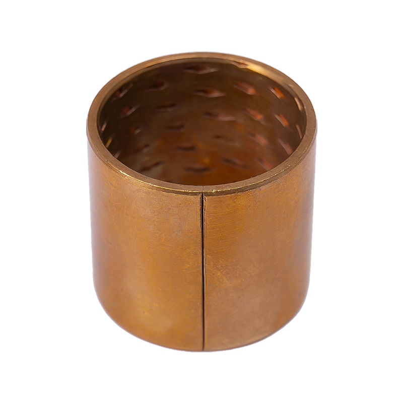 HZ090 Tin Bronze Oil-Groove Monometallic Copper BushingThin-wall tin bronze bushing with oil holes and grooves to store grease, designed for medium-to-high load, low-speed, humid, and high-temperature conditions.View Product →
Housing Tolerance Classes at a 25 mm Bore
Tolerance bands turn a single interference figure into a range, and that range is what the shop actually lives with. The comparison below assumes a bushing outside diameter at nominal, which keeps the arithmetic readable. Combine both bands in the calculator to see the real spread your process will produce. Negative values are clearance.
Interference ranges assume a bushing outside diameter at nominal zero deviation and a bronze modulus of 110 GPa. Always combine the bushing band and the housing band for the true minimum and maximum fit.
Where Press Fits Actually Fail
Repair and warranty feedback clusters into a small number of causes, and the ranking rarely surprises the people who assemble the parts. The pattern below reflects workshop observation rather than an audited survey, but the order stays consistent: the joint usually fails because of what pressing did to the geometry, not because the wrong bushing grade was chosen.
Bore distortion leads the list because it is invisible on the bench. The housing squeezes unevenly around a thin wall, the installed bore goes out of round, and the shaft runs on two narrow strips instead of a full contact arc. Over-interference is close behind and is almost always a tolerance stack problem, not a design intention.
Application Mix for Self-Lubricating Bushings
Press-fit bushings end up in a fairly predictable spread of industries. Treat the split below as indicative of a typical order book rather than an audited market study, and note that the automotive share is driven mainly by suspension, steering and pedal pivots where the bushing works without a recirculating oil supply.
- 38% Automotive suspension and steering
- 27% General industrial machinery
- 15% Agricultural and construction equipment
- 12% Material handling and logistics
- 8% Electrical and appliance mechanisms
The practical consequence is that a single interference target rarely covers a whole catalogue. A shock absorber eye bushing in a welded steel tube tolerates far more interference than a precision linkage bushing in an aluminium housing, even when the bore diameters are identical.
From Calculator Output to a Repeatable Process
A calculated interference is only useful if the shop can hit it every time. Working through these five steps in order keeps the design intent and the assembly reality aligned.
Define the duty cycle
Radial load, sliding speed, operating temperature, contamination and target life. A joint that survives installation but starves the sliding surface still fails, so the press fit and the bearing calculation have to agree.
Pick material and wall thickness
Solid bronze for high load at moderate speed, steel-backed bimetal or PTFE-lined for thin walls and higher PV, engineering plastic where corrosion and edge loading dominate.
Set the interference target
Aim for 0.05 to 0.10 percent of bore for solid bronze bushings, and 0.02 to 0.06 percent for thin-wall wrapped bushings. Convert the target back into a tolerance class before releasing the drawing.
Check stress and press force
Keep bore hoop stress under a third of the housing yield strength, and confirm the press force is inside the capacity of the equipment and the fixture that will do the work.
Verify on the first article
Measure the bore before and after pressing, check the installed inside diameter, and run a push-out test. Record the press force curve and keep it with the process sheet.
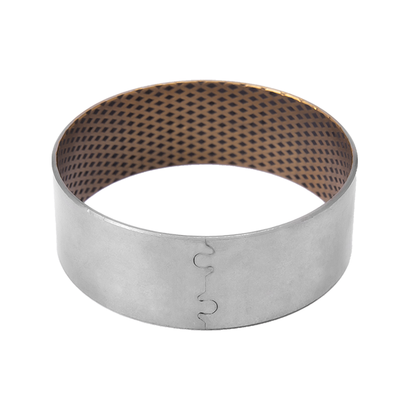 HZ08G Bimetallic Graphite Copper BushingCustom HZ-800 bimetal bushing with embedded graphite lubricant, high load capacity, and 260°C resistance for automotive, crane, and metallurgical machinery.View Product →
Installation, Maintenance and Compliance Notes
Most of the remaining risk sits in four habits that cost almost nothing to adopt.
- Guide the bushing in square. Half a degree of tilt roughly doubles the local contact pressure on one side of the bore and is a common source of housing cracks.
- Lubricate the outside diameter with light oil or assembly paste. Keep grease away from PTFE-lined bores, which are designed to run dry and can trap debris if coated.
- Expect the bore to close. A pressed bushing loses between 0.5 and 1.5 times the interference in inside diameter, so ream or size after installation whenever interference exceeds about 0.1 percent of bore.
- Document the force curve. A smooth rise to a plateau indicates a sound fit; a sudden drop usually means the bushing has sheared or the housing has yielded.
On the compliance side, wrapped bushes are normally specified against ISO 3547, while dimensional practice for plain bearings follows DIN 1494 or ISO 4379 depending on the region. For automotive programmes, ask for material certificates, dimensional inspection reports and PPAP-style documentation rather than accepting a catalogue number alone. Storage matters as well: keep bronze parts dry and free of condensation, and keep polymer-lined parts away from UV exposure and sustained heat. If your application combines a steel backing with a bronze overlay, the bimetal composite bearings guide explains how load and speed limits shift with that construction.
Run the calculator twice, once with the minimum material condition and once with the maximum, and the press fit stops being a guess. The interference you specify is a manufacturing commitment, and the hoop stress it creates is a property of the housing you already have.
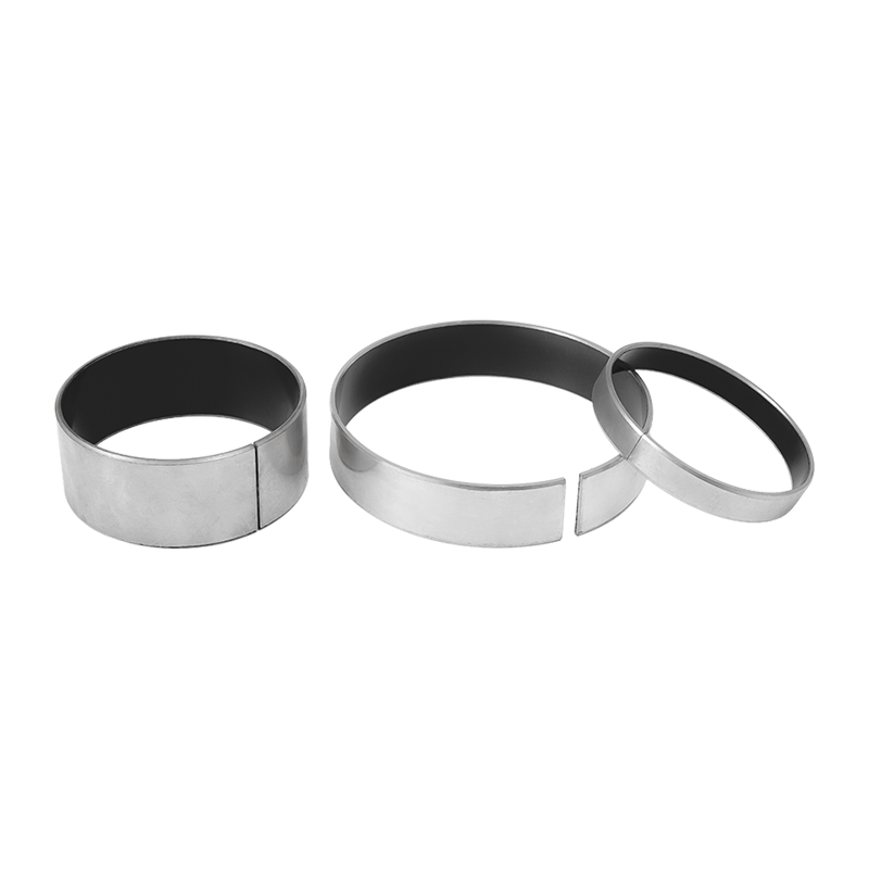 HZ10 Type 1 Steel-Based Self-Lubricating BearingSteel-backed PTFE/lead self-lubricating bearing for low-friction, low-noise sliding in printing, textile, fitness, pump, and office equipment.View Product →