English
 русский
 Español
 عربى
عربى
A stamping press on an automotive shock-absorber line started chirping at the beginning of every morning shift. Teardown found a 25 mm shaft journal worn into roughly 0.2 mm of ovality, and the replacement bushing was three weeks out. The maintenance team cleaned the journal, wrapped it with a thin PTFE fabric bearing tape, reassembled the press, and had it running again by the afternoon. That is what bearing tape does: it is a roll-form sliding layer, not bundling tape and not a sealing material. Choose the wrong thickness or the wrong fixing method, however, and it may not survive a single shift.
Four conclusions worth reading before you order
- Service life is set by thickness tolerance, fixing method and running clearance, not by how slippery the surface feels. A 0.05 mm thickness variation can consume half of your available fit clearance.
- Bronze-mesh PTFE soft belt normally runs 1.0 to 2.5 mm thick and must be press-fitted or rolled in. Adhesive PTFE fabric tape is mostly under 0.5 mm and suits light load or emergency repair only.
- Calculate PV (pressure times velocity) first. Most self-lubricating tapes hold a continuous PV of roughly 1.0 to 3.6 MPa m/s; beyond that, the wear rate climbs steeply.
- If operating temperature stays above 120 °C, or shaft roughness is coarser than Ra 0.8 micron, expect shortened life regardless of the tape grade you buy.
Content
- 1 What Bearing Tape Actually Is: A Sliding Layer, Not Adhesive Tape
- 2 What Actually Drives Friction and Wear
- 3 Comparing the Four Common Bearing Tape Forms
- 4 Hidden Metric: Relative Wear Life Under Real Duty Cycles
- 5 Where Bearing Tape Is Actually Used
- 6 Selection and Fitting Sequence
- 7 The Cost Math: When Tape Beats a New Part
- 8 Maintenance, Inspection and Compliance Notes
What Bearing Tape Actually Is: A Sliding Layer, Not Adhesive Tape
Bearing tape is an umbrella term for materials supplied in roll or strip form that end up as the low-friction surface inside a friction pair. In purchasing terms it covers four distinct product families, and they are not interchangeable.
- Bronze-mesh PTFE soft belt - sintered bronze spheres bonded to a steel or copper backing and impregnated with PTFE plus fillers. At 1.0 to 2.5 mm it is a structural material, pressed or rolled into a housing and used for wrapped bushings and loaded guideways.
- Self-adhesive PTFE fabric tape - thin woven fabric with an acrylic backing adhesive, 0.08 to 0.25 mm thick, used on linear guides, slider faces and field repairs.
- Engineering plastic sliding film - POM, UHMW-PE or PA strip at 0.3 to 1.0 mm, chosen for washdown, dust or food-contact areas.
- Graphite-filled polymer strip - solid lubricant embedded in a polymer matrix for slow, heavy and hot duties.
All four work the same way at the surface: they transfer a lubricating film onto the counterface. What separates them is how much load the backing can carry and how the strip is held in place. A tape that relies on adhesive cannot carry the pressure of a belt that is mechanically locked into a bore.
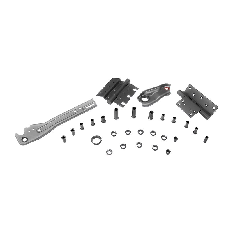 HZ-FR Bronze Wire Mesh PTFE Soft Belt BearingBronze wire mesh backing with sintered PTFE makes this flexible belt suitable where load support, low friction, and controlled thickness matter.View Product →
Thickness is the specification buyers underestimate most. Bearing tape occupies clearance that was originally designed for a solid bushing, so the wall thickness you select directly reduces the space left for thermal expansion and for the PTFE transfer film. Choosing a 2.0 mm belt where the housing was bored for a 1.5 mm wall leaves the shaft running tight from day one, and no amount of running-in will recover that interference.
What Actually Drives Friction and Wear
Bearing tape is not a plug-and-play spare. Its friction coefficient and life come out of six variables, and each one should be confirmed before the order is placed.
Backing material
Steel backing resists higher compressive stress; copper backing conducts heat away faster. Above roughly 50 MPa of surface pressure, steel-backed belt is the safer choice.
Working layer
PTFE migrates onto the shaft and forms a transfer film. Graphite needs a trace of moisture. POM expects a thin oil film. Match the layer to the environment, not to the catalogue photo.
Thickness tolerance
A belt held to plus or minus 0.02 mm behaves very differently from one held to plus or minus 0.08 mm once it is pressed into a housing.
Fixing method
Adhesive suits thin strip and light load. Press fitting suits thick belt and heavy load. Rolling suits wrapped bushings. Mixing these up is the most common field failure.
Counterface roughness
PTFE-based tape works best between Ra 0.2 and 0.8 micron. Too smooth and the film will not form; too rough and the working layer is planed away.
Running clearance
A taped bearing usually needs 1.5 to 2 times the clearance of an equivalent metal bushing, to leave room for heat growth and film build-up.
Comparing the Four Common Bearing Tape Forms
PV figures are typical continuous limits for dry or marginally lubricated running; always derate them for elevated temperature, contaminated media or shock loading.
Hidden Metric: Relative Wear Life Under Real Duty Cycles
Laboratory friction numbers rarely survive contact with a real machine. In field comparisons on comparable shaft diameters, load and lubrication, the relative wear life of bearing tape options separates clearly:
The pattern is consistent: adhesive-mounted thin tape loses life fastest when starved of lubrication, while the mechanically locked bronze-mesh belt outlasts even a well-greased bronze bushing because it keeps a permanent solid lubricant reservoir at the contact point.
Where Bearing Tape Is Actually Used
Demand for bearing tape clusters around applications where re-lubrication is difficult, unwelcome or simply impossible. The approximate distribution across industrial sectors looks like this:
- 38% Automotive - shock absorbers, seat mechanisms, pedal pivots and steering components, where the part must stay quiet for the life of the vehicle.
- 27% General machinery and linear motion - guideways, slides, hydraulic cylinders and packaging cams.
- 18% Heavy equipment - low-speed, high-load pivot points on construction and agricultural machinery.
- 11% Food and packaging - washdown areas where grease is not permitted.
- 6% Other - marine, rail and specialty equipment.
Selection and Fitting Sequence
Most premature bearing tape failures trace back to a skipped step rather than a bad material. Working in this order removes the guesswork:
Calculate PV and set a clearance target
Measure shaft diameter, bore, load and speed. Multiply pressure by velocity, then compare the result against the tape datasheet. Target 1.5 to 2 times the clearance of the equivalent solid bushing.
Inspect the counterface
Check roughness, hardness and roundness. Remove burrs, spiral turning marks and any embedded debris. A shaft that has already worn oval will not give the tape a uniform film to build on.
Choose the fixing method
Strip under 0.3 mm should be bonded; belt from 1.0 mm upward should be pressed or rolled in. Where a thin polymer layer is bonded to a slider face, a dedicated sliding film keeps the adhesive line out of the wear path.
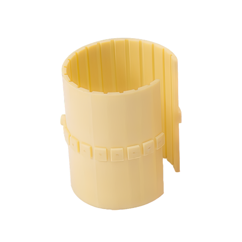 HZ-LIN Engineering Plastic Sliding Film for Bearing SurfacesFiber-reinforced polymer film with embedded PTFE and graphite provides self-lubricating, corrosion-resistant performance for cut-to-size sliding wear surfaces.View Product →
Cut square and deburr
Use a sharp blade, keep the cut perpendicular to the strip axis, and break the edges lightly with a fine file. A lifted edge will peel once the film starts forming.
Run in gently
Two to four hours at low load and low speed lets the transfer film establish before full duty is applied. Skipping this step is the usual cause of a tape scoring the shaft in the first shift.
If you are still deciding between a fully self-lubricating layer and one that expects occasional oil, our notes on self-lubricating and boundary-lubricated bearings explain where each one belongs.
The Cost Math: When Tape Beats a New Part
On a single small machine the saving is modest; on a production line it is not. Assume a replacement bushing costs about 12 USD, a press stop costs roughly 400 USD per hour, and a full bushing change takes four hours. A taped repair that holds for another 1,500 running hours typically takes one hour of labour, which frees two to three hours of production time. That is the entire business case.
The same logic works at volume. Belt and strip bought in roll form can be cut to the exact circumference needed, which trims offcut waste by roughly 30 to 40 percent compared with ordering fixed-size bushings for every variant. The condition is honest assessment: if journal ovality already exceeds about 0.1 mm, tape is a stopgap, not a repair. It buys you time to schedule the proper fix, and it should be treated that way.
Maintenance, Inspection and Compliance Notes
- Inspect at every planned shutdown, or every 500 to 1,000 running hours on continuous duty. A dark, glossy track on the surface is normal transfer film; exposed backing means the layer is finished.
- Re-check clearance after the first 200 hours. The film adds a small amount of thickness before it stabilises, and an initially correct fit can turn tight.
- Many bronze-mesh PTFE belts contain lead as a filler. For applications covered by RoHS or end-of-life vehicle restrictions, ask the supplier for a lead-free grade and get the declaration in writing.
- Store rolls away from direct sunlight between 5 °C and 30 °C. Adhesive-backed tape absorbs moisture and loses tack if it is kept in an open workshop.
- Record supplier batch, strip thickness and installation date for each repair. When the same joint fails twice, the batch record tells you whether it is a material problem or a fit problem.
Bearing tape rewards buyers who treat it as an engineered clearance item rather than a consumable. Measure the joint, calculate the PV, match the fixing method to the thickness, and the strip will outlast the part it replaced, exactly as it did on that shock-absorber line.