English
 русский
 Español
 عربى
عربى
A maintenance engineer once asked us why a bronze bushing in a conveyor drive kept failing every three months. Shaft alignment was within tolerance, the radial load calculation was correct, and the housing bore was properly machined. What nobody had verified was the axial thrust generated by the helical gear mesh — roughly 2.8 kN pushing the shaft against the end face of the bushing at every start and stop. That single overlooked load direction caused the fretting marks, scoring, and eventual seizure visible in the teardown photos.
Content
- 1 Axial Load Definition: What the Engineering Spec Actually Says
- 2 Axial Load vs. Radial Load: Side-by-Side Comparison
- 3 Combined Axial Load and Bending: When the Force Is Eccentric
- 4 Axial Load in Bearing Selection: Matching Component to Force Direction
- 5 Comparing Axial Load Capacity Across Material Systems
- 6 Where Axial Load Drives Bearing Decisions: Industry Distribution
- 7 Axial Load Evaluation: A Five-Step Selection Walkthrough
- 8 Maintenance and Compliance Checks for Axially Loaded Assemblies
Axial Load Definition: What the Engineering Spec Actually Says
An axial load is a force whose line of action passes through the centroid of a cross-section and runs parallel to the longitudinal axis of the member. It appears in two forms: tension, which pulls the member apart, and compression, which pushes it together. A building column supporting vertical floor loads, the connecting rod in a reciprocating compressor, and the pushrod in a valve train are all members dominated by axial loading.
The governing formula is straightforward. Normal stress equals the axial force divided by the cross-sectional area:
where P is the axial force and A is the original cross-sectional area. The resulting change in length follows from Hooke's law:
where L is the original member length and E is the elastic modulus of the material. When the force line shifts away from the centroid by some eccentricity e, the load is no longer purely axial; it becomes a combined axial-plus-bending problem that produces maximum stress at the edge of the cross-section. In rotating machinery, this is exactly the situation that breaks bearings.
Axial Load vs. Radial Load: Side-by-Side Comparison
Radial and axial loads place fundamentally different demands on a bearing surface. The differences that matter most during selection are summarized below.
The distinction matters because compact assemblies such as gearboxes, hydraulic pumps, and electric motor bell housings generate both force directions from the same element. A helical gear, for example, produces axial thrust proportional to the helix angle and the transmitted torque; if the design does not capture that thrust, the shaft will move axially until it finds an unintended load path.
Combined Axial Load and Bending: When the Force Is Eccentric
In real applications, axial load rarely passes exactly through the centroid. Eccentricity e converts the load into a combined axial-plus-bending problem, and the maximum stress becomes:
Three situations dominate industrial failures:
Misaligned mounting
A shaft tilted by even 0.5° relative to the bushing bore shifts the contact line and multiplies local edge pressure several times over the nominal average.
Slender member buckling
Long, thin shafts under pure compression can buckle below the yield stress. Euler's critical load predicts this; it is why tie rods and pushrods are sized on slenderness, not just on σ = P/A.
Thermal expansion thrust
Long rotating shafts that heat up during operation expand axially. Without end float allowance, the expansion force becomes an uncontrolled axial load at every operating cycle.
Axial Load in Bearing Selection: Matching Component to Force Direction
When axial load is present, three bearing categories cover most requirements: thrust washers for pure axial force, flanged bushings for combined radial and axial force, and self-lubricating bearings for maintenance-free service.
Pure axial thrust: thrust washers
When the shaft pushes axially with little or no radial component, a thrust washer is the most direct and cost-effective solution. The flat annular face distributes the load over a large contact area, and a hardened steel or bronze base provides predictable wear life. A properly selected washer handles continuous sliding duty and momentary shock peaks without scoring the housing face. The thrust washer selection guide covers load ratings and material choices in more detail.
Combined radial and axial: flanged bushings
Many shafts carry both radial and axial force from the same gear mesh or pulley arrangement. A flanged bushing handles both directions in one component: the bore supports the radial load and the flange face absorbs the axial component. This reduces part count and eliminates extra housing machining. Flanged designs also help reduce axial displacement in rotating shafts, a common issue in gearboxes and conveyor drives.
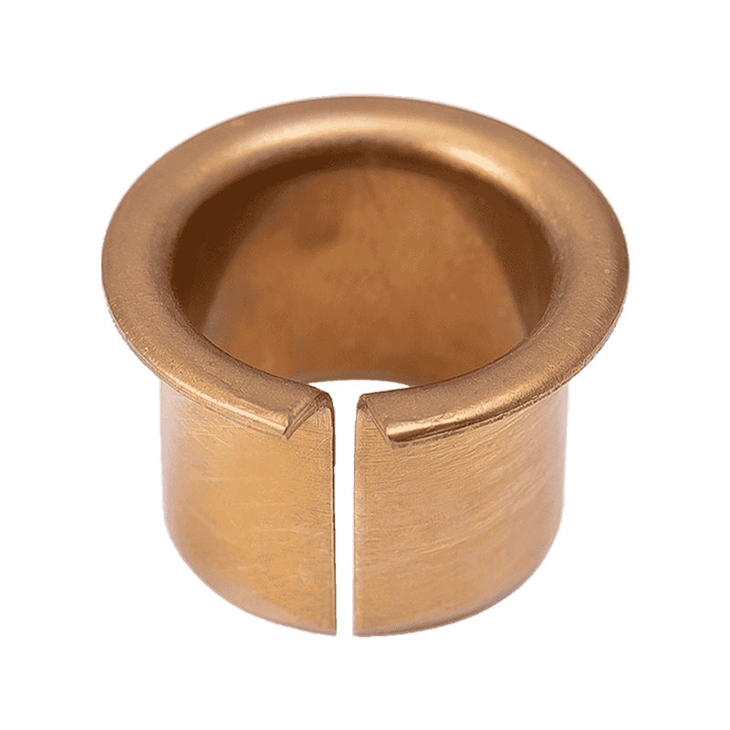 HZ093 Bronze Flanged Bushing for Radial and Axial SupportThis bronze flanged bushing handles both radial and axial loads in one component, reducing part count. Its corrosion-resistant material suits low-to-medium load, low-speed applications like conveyor rollers and linkages, and the flange helps prevent axial drift.View Product →
Maintenance-free operation: self-lubricating steel-backed bearings
For start-stop machinery, robotic linkages, and hard-to-reach pivot points, a steel-backed self-lubricating bearing with PTFE or inorganic fillers eliminates the need for re-greasing. The embedded solid lubricant transfers a film to the shaft, keeping friction low even at reduced sliding speeds. Axial loads in these applications are usually moderate, and the low-speed wear behavior is what makes self-lubricating materials a reliable choice.
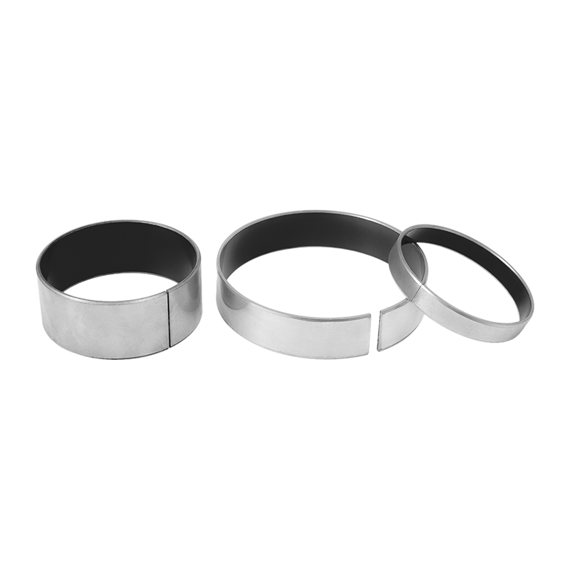 HZ10 Steel-Based Self-Lubricating Bearing with PTFE LayerThis steel-backed bearing features a sintered bronze interlayer and a PTFE compound surface for maintenance-free operation. It suits start-stop machinery and hard-to-reach pivot points, offering low friction and wear under moderate axial loads at reduced speeds.View Product →
Comparing Axial Load Capacity Across Material Systems
The chart below normalizes the static axial load capacity of common bushing material systems. Values are indicative for a 20 mm bore, 2 mm wall, at ambient temperature without additional lubrication.
Two observations stand out. Steel-backed PTFE systems top the axial load table because the steel substrate carries the structural load while the PTFE layer manages friction. And any material with a solid lubricant inlay — graphite, PTFE, or POM — outperforms plain plastic under sustained axial pressure because the lubricant film prevents cold flow and edge deformation.
Where Axial Load Drives Bearing Decisions: Industry Distribution
Based on application inquiries we handle and published failure analyses, the share of bearing selections dominated by axial load breaks down roughly as follows:
Automotive dominates because gearboxes, drive shafts, and electric power steering all generate continuous axial thrust. Industrial machinery follows closely, with helical and bevel gear units being the most frequent axial sources. In construction equipment, oscillation rather than rotation produces repetitive axial impact that accelerates face wear.
Axial Load Evaluation: A Five-Step Selection Walkthrough
Step 1 — Map the load path
Trace every force source: gear helix, belt tension, taper fit, thermal expansion. Draw the load path on a free-body diagram of the shaft.
Step 2 — Quantify the force
Calculate from transmitted power, helix angle, and service factor. Include dynamic peaks from startup shock if the drive accelerates quickly.
Step 3 — Choose architecture
Pure axial → thrust washer. Combined axial + radial → flanged bushing or angular contact. High speed → thrust ball or roller bearing.
Step 4 — Verify material limits
Compare calculated contact pressure against the material's rated PV limit. Account for sliding speed, temperature, and whether lubrication is continuous or intermittent.
Step 5 — Confirm alignment
Ensure the housing face is square to the shaft axis and that the flange or washer has a hardened backing surface. Misalignment concentrates axial stress at one edge.
Maintenance and Compliance Checks for Axially Loaded Assemblies
Inspection checklist
- Check end play regularly. An increase of more than 0.10 mm on a 40 mm shaft usually indicates flange or washer face wear.
- Look for scoring on the thrust face; polished wear is normal, but deep grooves signal contamination or edge loading.
- Verify that the shaft shoulder radius clears the bushing chamfer. A sharp shoulder edge can act as a cutting tool on the flange.
- Confirm the lubrication regime matches the manufacturer's PV rating. Dry-running materials must not be oil-lubricated if the design relies on solid lubricant transfer.
Standards and rating references
Axial load ratings for rolling bearings follow ISO 76 for static load and ISO 281 for dynamic load, expressed as C0a and Ca respectively. For plain and self-lubricating bushings, PV limits and wear coefficients are not yet harmonized into a single global standard; reputable manufacturers publish test-based ratings that should be compared under identical test conditions. When a compliance document is required for automotive, aerospace, or food processing applications, request the supplier's material certificates and validation test reports before approving serial production.