English
 русский
 Español
 عربى
عربى
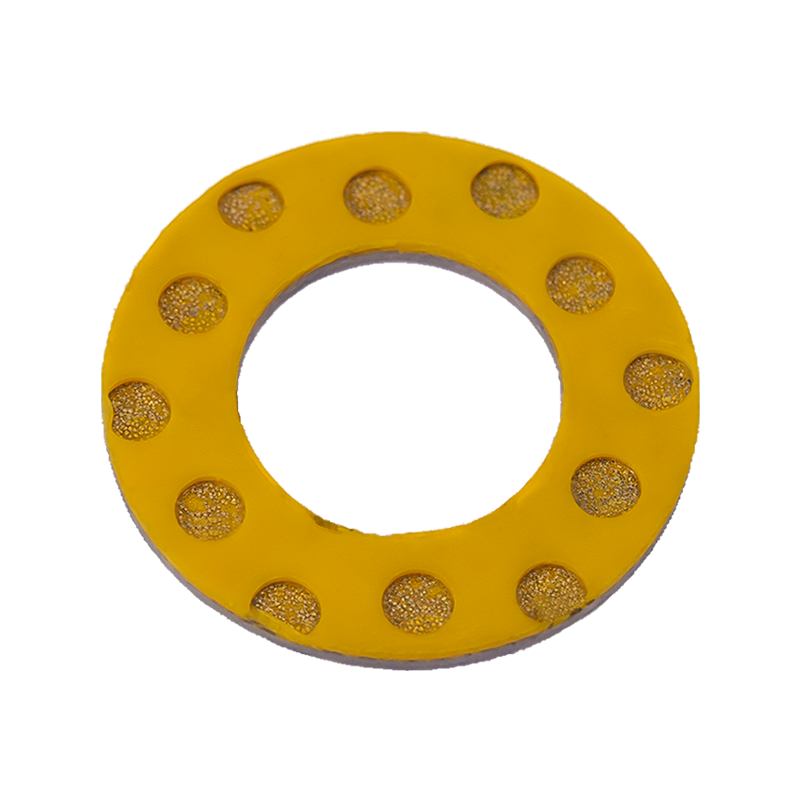
A thrust washer is a precision-engineered component designed to absorb axial loads and prevent lateral movement in mechanical assemblies. These flat, disc-shaped elements serve as critical interfaces between rotating and stationary parts, providing wear-resistant surfaces that maintain alignment under significant mechanical stress. Typically manufactured from hardened steel, bronze alloys, or advanced composite materials, thrust washers function as essential load-bearing elements in equipment ranging from small electric motors to massive industrial gearboxes.
The fundamental purpose of thrust washers extends beyond simple spacing or surface protection. Unlike conventional washers that primarily distribute fastener pressure, these specialized components actively manage axial forces generated during equipment operation. When shafts experience thrust loads along their longitudinal axis, thrust washers absorb and distribute these forces, preventing metal-to-metal contact that would otherwise result in rapid wear, galling, or catastrophic component failure. This load management capability makes them indispensable in applications where precise shaft positioning directly impacts equipment performance and longevity.
Content
Operating Principles and Load Management
Thrust washers function by creating a low-friction boundary between components that experience relative motion under axial loading. The working surface of the washer must simultaneously provide adequate load capacity and minimize frictional resistance. This dual requirement drives material selection and surface engineering decisions that distinguish high-performance thrust washers from standard hardware components.
The installation configuration typically positions thrust washers between a rotating shaft shoulder and a stationary housing surface, or between two rotating components with relative axial movement. As operational loads apply pressure across the washer face, the material's compressive strength prevents plastic deformation while its surface properties facilitate smooth sliding contact. Properly specified thrust washers maintain consistent friction coefficients throughout their service life, ensuring predictable equipment behavior and controlled energy dissipation.
Lubrication plays a critical role in thrust washer performance. Oil or grease films separate the contacting surfaces under hydrodynamic or boundary lubrication regimes, depending on operating speeds and loads. Some applications utilize self-lubricating thrust washers incorporating polytetrafluoroethylene (PTFE), graphite, or molybdenum disulfide embedded within the base material. These compositions eliminate external lubrication requirements, simplifying maintenance and enabling operation in inaccessible or contamination-sensitive locations.
Material Selection Criteria
The operational environment dictates appropriate material choices for thrust washer applications. Steel-backed bronze washers offer excellent load capacity and conformability, making them suitable for heavy-duty industrial equipment. The bronze surface layer embeds foreign particles to prevent scoring of mating surfaces, while the steel backing provides structural support. Hardened steel washers withstand higher contact pressures and elevated temperatures, though they require harder mating surfaces to prevent mutual wear.
Composite thrust washers combine engineering plastics with reinforcing fibers to achieve specific performance characteristics. PTFE-based materials provide exceptionally low friction coefficients and chemical resistance, enabling use in corrosive environments or food-processing equipment where contamination must be avoided. These polymer composites typically operate at lower load capacities than metallic alternatives but offer advantages in weight reduction and galvanic compatibility with aluminum housings.
Crankshaft Thrust Washer Applications
The crankshaft thrust washer represents a specialized application of thrust washer technology in internal combustion engines. Positioned at specific locations along the crankshaft axis, these components control axial movement of the crankshaft relative to the engine block. This positioning function proves critical for maintaining proper engine timing, ensuring consistent valve train operation, and preventing contact between rotating and stationary engine components.
In automotive and industrial engines, the crankshaft thrust washer typically takes the form of semi-circular or C-shaped segments that install into machined grooves in the engine block or main bearing caps. This split design facilitates assembly and replacement without complete engine disassembly. The washer faces contact precision-ground surfaces on the crankshaft counterweights or specially machined thrust surfaces, creating a bearing interface that accommodates the axial loads generated during engine operation.
The primary load source for crankshaft thrust washers originates from clutch engagement in manual transmission vehicles. When the driver depresses the clutch pedal, the release bearing applies force to the pressure plate diaphragm spring, creating a reaction force transmitted through the clutch assembly to the crankshaft. Without adequate thrust bearing capacity, this force would drive the crankshaft forward, potentially damaging timing components, oil seals, or the transmission input shaft. The crankshaft thrust washer absorbs these loads, maintaining crankshaft position within specified end-play tolerances.
Engine-Specific Design Considerations
Crankshaft thrust washer design must accommodate the unique thermal and mechanical environment of internal combustion engines. Operating temperatures near combustion chambers expose these components to oil temperatures exceeding 120°C, requiring materials that maintain strength and wear resistance at elevated temperatures. Copper-lead alloys and aluminum-tin compositions provide excellent high-temperature performance, while steel-backed babbitt metal offers good embeddability and compatibility with steel crankshaft surfaces.
The width and thickness of crankshaft thrust washers require precise calculation based on anticipated loads and allowable wear rates. Insufficient bearing area concentrates contact pressures, accelerating wear and potentially causing localized overheating. Excessive clearance permits crankshaft movement that disrupts timing relationships and generates objectionable noise. Manufacturers specify end-play dimensions typically ranging from 0.05 to 0.30 millimeters, requiring thrust washers manufactured to tight tolerances for proper fit and function.
Common Applications Across Industries
Thrust washers serve critical functions across diverse industrial sectors. In gearboxes and transmission systems, they position shafts and gears to maintain proper mesh alignment while accommodating axial reaction forces generated by helical gear tooth profiles. These applications often utilize multiple thrust washers in series to distribute loads across larger surface areas or to provide redundant load paths for enhanced reliability.
Rotating equipment such as pumps, compressors, and turbines incorporate thrust washers to manage axial loads imposed by fluid pressure differentials or impeller thrust. Vertical pump applications particularly depend on thrust washers to support the weight of rotating assemblies while accommodating hydraulic thrust loads that vary with operating conditions. The washers in these applications often operate in fluid environments, requiring materials resistant to corrosion and cavitation damage.
Electric motors and generators utilize thrust washers in bearing arrangements that must accommodate magnetic centering forces or rotor weight in vertical configurations. These applications frequently specify insulated thrust washers to prevent electrical current passage through bearing surfaces, which would cause destructive pitting and premature failure. Composite materials or ceramic coatings provide electrical isolation while maintaining mechanical load capacity.
Industrial Application Comparison
| Application | Primary Load Type | Common Material | Key Requirement |
| Automotive Engine | Clutch thrust | Copper-lead alloy | High temperature resistance |
| Gearbox | Gear reaction force | Steel-backed bronze | Fatigue resistance |
| Vertical Pump | Rotor weight + hydraulic | PTFE composite | Corrosion resistance |
| Electric Motor | Magnetic thrust | Insulated composite | Electrical isolation |
| Wind Turbine | Yaw bearing thrust | Hardened steel | Impact load capacity |
Failure Modes and Prevention Strategies
Thrust washer failures typically manifest as excessive wear, scoring, cracking, or complete material displacement. Understanding failure mechanisms enables specification of appropriate materials and maintenance practices to maximize service life. Contamination represents the most common cause of premature thrust washer failure, as hard particles embedded in contact surfaces generate abrasive wear and localized stress concentrations.
Misalignment between thrust washer faces and mating surfaces creates uneven load distribution that accelerates wear in high-contact areas. Installation procedures must ensure parallel surfaces and proper seating within housings or retaining grooves. Thermal expansion differences between dissimilar materials can induce distortion under temperature cycling, requiring design clearances that accommodate dimensional changes without binding.
Overloading beyond design capacity causes plastic deformation or fracture of thrust washer materials. Safety factors in thrust washer selection must account for peak loads, impact forces, and potential system malfunctions that generate higher-than-normal axial forces. Regular monitoring of end-play dimensions in critical applications such as crankshaft thrust washers enables predictive maintenance before catastrophic failure occurs.
Maintenance and Replacement Indicators
Monitoring thrust washer condition requires attention to operational symptoms that indicate degradation. Increased axial shaft movement, unusual noise during load reversals, or elevated operating temperatures may signal thrust washer wear. In engines, excessive crankshaft end-play manifests as clutch pedal pulsation or difficulty shifting gears, indicating crankshaft thrust washer replacement requirements.
Replacement thrust washers must match original specifications for material, dimensions, and surface finish. Mixing materials with different wear rates or thermal expansion characteristics can create compatibility issues that accelerate failure. Proper cleaning of housing grooves and shaft surfaces during installation prevents contamination that would immediately compromise the new bearing surfaces.
The selection and application of thrust washers requires understanding of load characteristics, environmental conditions, and compatibility with mating components. Whether managing the critical positioning of a crankshaft in a high-performance engine or supporting axial loads in industrial rotating equipment, properly specified thrust washers ensure reliable operation and extended equipment life. Their seemingly simple geometry conceals sophisticated engineering that enables modern machinery to achieve the performance and durability standards demanded by industry.