English
 русский
 Español
 عربى
عربى
Assembly space is a finite resource in mechanical design, and bearing selection is one of the first places engineers look when they need to recover it. A thin wall copper bushing offers a specific solution: the structural performance of a solid bronze sleeve bearing in a radial wall thickness that can be half—or less—of an equivalent cast bushing. For machine designers working on agricultural equipment, construction machinery, or automotive linkages, that difference is often the margin between a component that fits and one that requires a housing redesign.
Content
- 1 Defining Thin Wall: What the Geometry Actually Means
- 2 How the Rolling Process Creates Superior Material Properties
- 3 Oil Pocket Design in Thin Wall Bushings: Engineering the Lubrication Surface
- 4 Thin Wall vs Standard Wall vs Cast: A Comparative Framework
- 5 Selecting the Right Thin Wall Copper Bushing: Key Parameters
- 6 Flanged Variants and Brass Options in the Thin Wall Range
- 7 Why Thin Wall Copper Bushings Are Replacing Cast Alternatives in Machinery OEM Design
Defining Thin Wall: What the Geometry Actually Means
The term "thin wall" in bearing engineering refers to the ratio of wall thickness to bore diameter, not to an absolute thickness value. A bushing with a 50 mm bore and a 3 mm wall is thin-wall; the same 3 mm wall on a 20 mm bore is relatively thick. The relevant standard for rolled thin-wall bronze bushings—DIN 1494 / ISO 3547—specifies wall thickness as a function of bore diameter, with the ratio typically falling in the range of 1:10 to 1:20 depending on the series.
This matters practically because thin-wall bushings can be installed in housings that are machined to tighter external dimensions, allowing the bearing to occupy minimal radial space while still presenting a full bronze contact surface to the shaft. In a compact pivot joint on a harvester header or a tight pin bore in an excavator boom, replacing a cast bushing with a rolled thin-wall equivalent can reduce the required housing bore diameter by several millimeters—enough to allow a thicker housing wall, a larger shaft, or simply a smaller overall assembly envelope.
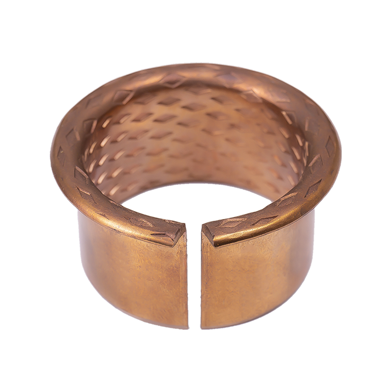
The HZ090 series single metal copper sleeve is built specifically around this thin-wall design philosophy: the sleeve is rolled from precision-drawn copper alloy strip to achieve wall uniformity that casting cannot match, and the compact cross-section allows it to be substituted directly into housing bores designed for standard ISO dimensions without enlarging the housing.
How the Rolling Process Creates Superior Material Properties
Thin wall copper bushings are not simply cast bushings machined to smaller wall thickness. They are manufactured by a fundamentally different process—cold-forming flat strip—that produces a different microstructure and different performance characteristics.
The process begins with hot-rolled copper alloy strip (most commonly CuSn8 phosphor bronze or CuSn6.5 tin bronze) that has been homogenized through the mill rolling process to achieve uniform alloying element distribution throughout the cross-section. The strip is then cold-formed around a precision mandrel into the cylindrical bushing shape, a step that introduces controlled work-hardening at the surface and maintains the dense, void-free grain structure of the original strip.
The contrast with casting is direct and measurable. Cast copper bushings solidify from a melt, and solidification inherently produces:
- Shrinkage voids: Micro-cavities that form as the liquid metal contracts during cooling, creating internal stress concentrations
- Segregation: Uneven distribution of alloying elements (tin, phosphorus) between grain boundaries and grain interiors, causing local variations in hardness and wear resistance
- Coarser grain structure: Slower cooling rates in casting produce larger grains, which are less resistant to fatigue crack initiation under cyclic loading
Rolled strip eliminates all three effects. The result is a bushing with higher density, no internal voids, and finer, more uniform grain structure—properties that translate to better fatigue life under the shock loads typical of agricultural and construction machinery pivot joints. For bearing buyers who specify on load rating alone, the microstructural difference may not be visible in the datasheet; it becomes apparent in field service life comparisons.
Oil Pocket Design in Thin Wall Bushings: Engineering the Lubrication Surface
The friction surface of a thin wall copper bushing is not a plain bore. It carries a precisely engineered pattern of oil storage features whose geometry is determined by the application's lubrication access, load level, and required service interval.
Three oil-feature types are standard on rolled copper bushings, and each serves a distinct lubrication function:
Diamond-shaped indentations are the most common configuration for thin-wall applications. Shallow rhombus-shaped pockets are pressed or machined into the inner bore surface in a uniform pattern that covers the full contact area. Each pocket holds a small volume of grease; as the shaft rotates or oscillates past the pocket, it draws lubricant out and spreads it across the contact zone. The pockets refill partially from adjacent areas under the squeeze-film effect of bearing load. This self-distribution mechanism is what allows properly filled diamond-pocket bushings to extend lubrication intervals significantly compared to plain-bore alternatives—reducing the frequency of re-greasing without compromising film integrity.
Cylindrical through-holes penetrate the full wall thickness and allow pressurized grease injection from a fitting in the housing bore directly to the shaft surface. This configuration is standard in construction machinery where high-pressure centralized lubrication systems are used. The through-hole pattern in a thin-wall bushing must be positioned to clear the housing interference zone—a design detail that the bushing manufacturer handles through standard hole placement patterns referenced to the bushing joint line.
Helical oil grooves are machined after rolling and provide a continuous channel for oil or grease distribution along the bearing length. They are most effective in applications with pure rotary motion at moderate speeds where hydrodynamic lubrication film development is possible. HZ090 tin bronze oil groove copper bushings use this configuration for applications requiring continuous oil film support across the full bearing length.
Thin Wall vs Standard Wall vs Cast: A Comparative Framework
Choosing between thin-wall rolled, standard-wall rolled, and cast copper bushings requires matching bearing characteristics to application requirements. The table below summarizes the key differentiators:
| Parameter | Thin Wall Rolled (HZ090) | Standard Wall Rolled | Cast Bronze |
|---|---|---|---|
| Wall thickness ratio | 1:10 to 1:20 (ID/wall) | 1:6 to 1:10 | 1:4 to 1:8 |
| Material density | High (no voids) | High (no voids) | Variable (shrinkage possible) |
| Fatigue resistance | Excellent | Excellent | Good to moderate |
| Assembly space required | Minimal | Moderate | Maximum |
| Cost per unit | Low–medium | Low–medium | Medium–high |
| Complex shapes | Limited | Limited | Good |
| Custom oil features | Excellent | Excellent | Moderate |
Cast bronze retains advantages for very large bore sizes (above ~200 mm), complex non-cylindrical geometries, and applications where very thick walls are structurally required. For the bore range most common in agricultural and construction machinery (20–120 mm) and at the wall thicknesses that fit modern compact housings, thin-wall rolled copper bushings cover the requirement more efficiently.
Selecting the Right Thin Wall Copper Bushing: Key Parameters
Specifying a thin wall copper bushing requires four inputs that together determine the correct product:
1. Bore diameter and shaft tolerance. The bushing inner diameter after installation—accounting for the press-fit elastic contraction that occurs when the bushing is pressed into a housing—must match the shaft diameter with the correct running clearance. For oscillating applications, clearance is typically H7/f7 or similar; for slow rotary motion, H7/e7. Thin-wall bushings deflect slightly more on pressing than thick-wall equivalents, so confirm final bore diameter against the manufacturer's installed-dimension data, not just the free-state nominal.
2. Specific load (PV value). The product of bearing pressure (P, in N/mm²) and sliding velocity (V, in m/s) defines the PV value, which must remain below the material's limit. CuSn8 phosphor bronze has a permissible dynamic load of approximately 40 N/mm² and a PV limit in grease-lubricated service of around 3–5 N/mm² · m/s, depending on oil pocket coverage and grease type. Agricultural machinery pivot joints typically operate well within these limits because velocities are low, but construction machinery swing bearings can approach the boundary under sustained operation.
3. Oil feature configuration. Match the oil pocket type to lubrication access. Diamond pockets for sealed or infrequent-access joints; through-holes for centralized grease systems; helical grooves for continuous oil-lubricated applications. The HZ090F flanged bronze bushing with diamond oil groove covers the most common combination—radial and axial load with extended lubrication intervals—in a single component.
4. Flange requirement. If the joint carries any axial load or requires precise axial location of the shaft, specify a flanged bushing. If the joint is purely radial and axial location is managed elsewhere in the assembly, a straight cylindrical sleeve saves radial space and simplifies pressing.
Flanged Variants and Brass Options in the Thin Wall Range
The thin wall copper bushing family extends beyond the basic cylindrical form. Two variants address common design requirements that the straight sleeve cannot fully satisfy on its own.
Flanged thin wall bushings integrate a collar at one end that provides an axial bearing surface in addition to the radial bore. For pivot pins in loader arms, hitch links, and hydraulic cylinder clevis joints—all of which experience axial forces from misalignment and side loading—the flanged bushing eliminates a separate thrust washer and the assembly step required to install it. The HZ093 bronze flanged bushing delivers this combined function in a rolled thin-wall construction with oil features on both the bore and the flange face.
Brass thin wall bushings provide a cost-effective alternative for applications where loads are moderate and material cost is a primary driver. The HZ62 brass bushing retains the thin-wall rolled construction benefits—high density, precise oil groove geometry, compact cross-section—while using a brass alloy that machines freely and costs less per kilogram than tin bronze. Brass is appropriate when operating loads are below the threshold where tin bronze's higher fatigue strength is needed and when shaft hardness and finish are controlled.
Why Thin Wall Copper Bushings Are Replacing Cast Alternatives in Machinery OEM Design
The shift from cast bronze bushings to thin-wall rolled copper sleeves in agricultural and construction machinery OEM programs has been steady over the past two decades, driven by three converging pressures: weight reduction targets, assembly space constraints from higher-density machine designs, and total cost of ownership comparisons that favor extended service intervals.
On the weight side, a thin-wall rolled bushing uses 20–40% less copper per unit than a cast equivalent of the same bore and length. Across a machine with 30–50 bearing points, that reduction adds up to meaningful mass savings that improve fuel economy and reduce transport costs for the finished machine.
On the cost side, rolled strip is a more economical raw material form than cast billets or centrifugally cast tubes, and the rolling and calibration process requires less machining than turning a cast blank to final dimensions. The combination of lower material input and simpler processing gives thin-wall rolled bushings a structural cost advantage that compounds at high production volumes.
For machine designers and procurement engineers evaluating the full bearing product range—from self-lubricating composites to bimetal construction to solid copper sleeves—the complete bearing and bushing product range provides a basis for systematic comparison across materials, configurations, and load ratings to find the right solution for each specific joint in a machine design.