English
 русский
 Español
 عربى
عربى
When conventional oil or grease lubrication is impractical — due to contamination risk, inaccessible locations, extreme temperatures, or maintenance-free design requirements — boundary-lubricated bearings and self-lubricating bearings are the engineered solution that eliminates the lubrication system entirely while maintaining acceptable friction and wear performance. These bearing types operate where a full hydrodynamic film cannot be sustained, relying instead on solid lubricant films, embedded lubricant reservoirs, or low-friction matrix materials to protect contact surfaces. Selecting the correct type and material for the specific load, speed, temperature, and environment determines whether the bearing achieves its design life or fails prematurely.
Content
- 1 What Boundary Lubrication Means and Why It Matters
- 2 How Self-Lubricating Bearings Work
- 3 Solid Lubricant Materials: Properties and Performance Comparison
- 4 Main Types of Self-Lubricating Bearings and Their Structures
- 5 PV Limit: The Critical Design Parameter for Boundary-Lubricated Bearings
- 6 Industries and Applications Where Self-Lubricating Bearings Are Essential
- 7 Shaft Material and Surface Finish: The Often-Overlooked Factor
- 8 Selecting the Right Self-Lubricating Bearing: A Practical Decision Framework
What Boundary Lubrication Means and Why It Matters
Lubrication regimes are classified by the Stribeck curve into three zones: hydrodynamic (full film), mixed, and boundary. In the boundary lubrication regime, the lubricant film is too thin to fully separate the bearing surfaces — film thickness is typically less than the combined surface roughness of the two contact faces, meaning asperity-to-asperity contact occurs directly between the shaft and bearing. Under these conditions, friction and wear are governed not by fluid viscosity but by the physical and chemical properties of the thin molecular lubricant layer adhering to the metal surfaces.
Boundary lubrication conditions arise at low sliding speeds, high contact pressures, during start-stop cycles, and at the moment of startup before a hydrodynamic film can form. Even bearings designed for full-film operation spend a portion of every operating cycle in the boundary regime. For applications that operate continuously at low speed under high load — linkages, pivots, construction equipment pins, agricultural machinery joints — the bearing may never escape the boundary regime during normal operation, making the material's boundary lubrication performance the defining factor in its service life.
The Stribeck Curve: Where Boundary Lubrication Occurs
| Regime | Film Thickness | Friction Coefficient | Wear Rate | Governing Factor |
|---|---|---|---|---|
| Hydrodynamic | >1 µm | 0.001–0.005 | Near zero | Fluid viscosity |
| Mixed | 0.1–1 µm | 0.01–0.10 | Low–moderate | Fluid + surface properties |
| Boundary | <0.1 µm | 0.05–0.20 | Moderate–high | Surface material chemistry |
How Self-Lubricating Bearings Work
Self-lubricating bearings achieve maintenance-free operation by incorporating solid lubricants directly into the bearing structure — either as embedded reservoirs that release lubricant progressively under contact pressure and heat, as a low-friction matrix material that forms a transfer film on the mating shaft surface, or as a surface coating of solid lubricant applied to a metallic substrate. The result is a bearing that continuously replenishes its own lubricant supply from within, without any external grease or oil system.
The most critical mechanism in self-lubricating bearing operation is transfer film formation. As the bearing operates, solid lubricant particles — typically PTFE, graphite, or molybdenum disulfide (MoS₂) — are transferred from the bearing surface onto the shaft. This thin transfer film, typically 0.01–0.1 µm thick, reduces the effective friction coefficient at the contact interface from 0.15–0.30 (metal-on-metal boundary contact) to 0.04–0.15, dramatically extending component life and reducing operating temperature.
Three Mechanisms of Self-Lubrication
- Embedded solid lubricant plugs or pockets: Machined recesses in a bronze or iron bearing matrix are filled with solid lubricant compacts — graphite, PTFE, or MoS₂. Under load and relative motion, the solid lubricant extrudes from the pockets and spreads across the contact surface. Graphite-plugged bronze bearings of this type are widely used in steel mill roll neck bearings, bridge expansion joints, and heavy construction equipment pivots, where service temperatures up to 300°C make conventional grease impractical.
- Impregnated porous metal bearings: Sintered bronze or iron powder is pressed and sintered to create a porous matrix with 15–30% void volume by design. This void volume is then vacuum-impregnated with oil. Under operation, thermal expansion and capillary action draw oil to the bearing surface; when stationary and cool, the oil is reabsorbed into the matrix. These oil-impregnated sintered bearings (commonly called oilite bearings) operate continuously without relubrication for their full service life in light-to-medium duty applications.
- Polymer matrix bearings: PTFE, PEEK, nylon, acetal, or composite polymer bearings contain solid lubricants uniformly distributed throughout the polymer matrix. As the bearing surface wears microscopically in service, fresh lubricant-loaded material is continuously exposed. PTFE-based composite linings — such as PTFE/glass fiber/MoS₂ composites — achieve friction coefficients as low as 0.04–0.08 in dry sliding, rivaling oil-lubricated metal bearings in many conditions.
Solid Lubricant Materials: Properties and Performance Comparison
The choice of solid lubricant determines the bearing's friction coefficient, operating temperature range, load capacity, and compatibility with the operating environment. The four primary solid lubricants used in boundary-lubricated and self-lubricating bearings each have distinct strengths and limitations.
| Lubricant | Friction Coefficient (dry) | Max Operating Temp | Load Capacity | Key Advantage |
|---|---|---|---|---|
| PTFE | 0.04–0.10 | 260°C | Low–Medium | Lowest friction; chemical inertness |
| Graphite | 0.08–0.15 | 450°C (air) / 2,500°C (inert) | High | High-temp performance; humidity-assisted lubrication |
| MoS₂ | 0.03–0.08 | 400°C (air) / 1,100°C (vacuum) | High | Excellent in vacuum and dry environments |
| h-BN (hexagonal boron nitride) | 0.10–0.20 | 900°C (air) | Medium | Extreme temperature; electrical insulation |
An important environmental dependency affects graphite and MoS₂ selection: graphite requires adsorbed water vapor or gas molecules to achieve low friction and performs poorly in dry vacuum environments, while MoS₂ performs best in dry or vacuum conditions and degrades more rapidly in high-humidity environments due to oxidation of the sulfide layers. This distinction is critical in aerospace and space applications — MoS₂ is the standard choice for satellite mechanisms and vacuum-operating equipment where graphite would exhibit high friction.
Main Types of Self-Lubricating Bearings and Their Structures
Self-lubricating bearings are manufactured in several distinct structural configurations, each optimized for different load levels, speed ranges, temperature requirements, and application environments. Understanding these structures clarifies which product category is appropriate for a given duty.
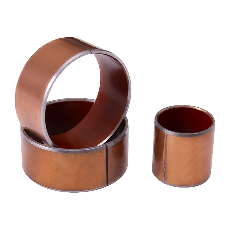
Bimetal Self-Lubricating Bearings
Bimetal self-lubricating bearings combine a steel backing for structural strength with a bronze alloy inner layer into which solid lubricant plugs (graphite or MoS₂) are embedded in a regular pattern. The steel backing handles the housing press-fit and structural load; the bronze matrix provides hardness and thermal conductivity; and the solid lubricant plugs cover 25–35% of the contact surface area, providing continuous lubrication across the bearing bore. These bearings carry static loads up to 250 MPa and operate continuously at temperatures from −40°C to 300°C, making them standard for construction machinery, agricultural equipment, and general industrial pivot applications.
PTFE Composite Lined Bearings
These bearings use a steel or bronze backing with a thin PTFE composite lining — typically 0.25–0.35 mm thick — bonded to the bore surface. The lining consists of PTFE mixed with reinforcing fillers such as glass fiber, carbon fiber, bronze powder, or MoS₂ to improve load capacity and reduce the inherent creep tendency of pure PTFE. The resulting bearing achieves friction coefficients of 0.04–0.12 in dry operation and is widely used in automotive chassis components (control arm bushings, stabilizer link bushings), aircraft control surface bearings, and precision instrument pivots where contamination or weight constraints prevent conventional lubrication.
Oil-Impregnated Sintered Metal Bearings
Produced by powder metallurgy from bronze (typically 90% copper, 10% tin) or iron powder, sintered bearings are pressed to controlled density, sintered at temperature, and then vacuum-impregnated with oil at 15–30% volume fraction. They are the most cost-effective self-lubricating bearing type for light-to-medium duty, widely used in electric motors, fans, small appliances, office equipment, and household devices. A well-specified oilite bearing operating within its PV (pressure-velocity) limit will provide maintenance-free service for the full product lifetime in applications running continuously at speeds from 50 to 3,000 RPM.
Engineered Polymer Bearings
Polymer bearings machined or injection-molded from filled PTFE, PEEK, UHMWPE, acetal, or nylon provide self-lubrication through the inherent low-friction properties of the polymer matrix. PEEK bearings are specified for the most demanding temperature and chemical resistance requirements — operating continuously to 250°C and resisting virtually all industrial chemicals, making them standard in chemical processing, food and beverage, and pharmaceutical equipment where metal contamination must be avoided and lubrication is prohibited.
PV Limit: The Critical Design Parameter for Boundary-Lubricated Bearings
The PV limit — the product of contact pressure (P, in MPa) and sliding velocity (V, in m/s) — is the fundamental design parameter for all boundary-lubricated and self-lubricating bearings. It defines the maximum combined loading and speed condition the bearing can sustain without the frictional heat generation exceeding the material's thermal limits and causing accelerated wear, softening, or catastrophic failure. Operating at or near the PV limit continuously will shorten service life significantly; sustained operation above the PV limit will cause rapid failure.
The PV limit is not simply additive — high pressure with low velocity may be acceptable while the same PV value achieved through moderate pressure and moderate velocity may generate more heat due to reduced cooling by shaft contact. Manufacturers publish PV limit curves showing the acceptable pressure-velocity operating envelope, and these should be consulted rather than using the peak PV value alone as the design criterion.
Typical PV Limits by Bearing Material
| Bearing Material | Max Static Load (MPa) | Max Speed (m/s) | PV Limit (MPa·m/s) | Max Temp (°C) |
|---|---|---|---|---|
| Bimetal (Steel/Bronze/Graphite) | 250 | 2.5 | 1.5 | 300 |
| PTFE Composite Lined | 140 | 3.0 | 0.10 | 260 |
| Sintered Bronze (Oil-Impregnated) | 60 | 6.0 | 1.8 | 120 |
| PEEK (filled) | 100 | 5.0 | 0.30 | 250 |
| Acetal (POM) | 60 | 3.0 | 0.10 | 90 |
Industries and Applications Where Self-Lubricating Bearings Are Essential
Self-lubricating bearings under boundary lubrication conditions are not a niche solution — they serve as the primary bearing type in a wide range of industries where the operating environment, maintenance requirements, or application geometry makes conventional lubricated bearings impractical or unacceptable.
Construction and Agricultural Equipment
Excavator boom and bucket pins, loader arm pivots, agricultural implement joints, and crane slewing ring interfaces all operate under high static load, oscillating motion, and heavy contamination. Greased bronze bushings at these locations require relubrication intervals as short as 8–50 operating hours — impractical in field conditions. Bimetal graphite-plugged self-lubricating bearings at these locations extend maintenance intervals to 1,000–5,000 hours, reducing lubricant consumption, labor cost, and contamination of surrounding soil and waterways.
Food, Beverage, and Pharmaceutical Processing
Regulatory requirements in food contact zones prohibit petroleum-based lubricants that could contaminate product. PTFE composite and PEEK polymer bearings in conveyor systems, filling machinery, packaging equipment, and mixing vessels provide maintenance-free operation without any lubricant that could reach the product stream. FDA-compliant PTFE and UHMWPE bearing materials are standard specifications in these industries, with zero lubricant migration risk and full compatibility with steam cleaning and chemical sanitization cycles.
Aerospace and Defense
Aircraft control surface bearings, helicopter rotor head bearings, and missile fin pivots operate under oscillating loads at variable temperatures from −65°C to 200°C with no opportunity for in-service relubrication. MoS₂-filled PTFE composite spherical bearings are the standard solution, providing service lives exceeding 20,000 flight hours in control surface applications. Satellite and spacecraft mechanisms use MoS₂-coated bearings specifically because the vacuum environment eliminates graphite's adsorbed-moisture lubrication mechanism, making MoS₂ the only viable solid lubricant in space.
Automotive Chassis and Powertrain
Suspension control arm bushings, steering rack bushings, stabilizer bar links, and clutch pivot bearings in modern vehicles are almost universally PTFE-lined self-lubricating bearings sealed for life. Replacing the greaseable bronze bushings used in earlier vehicle generations, these maintenance-free bearings are designed to last the full vehicle service life of 250,000–300,000 km without relubrication, eliminating a service item that many vehicle owners would neglect, and reducing warranty claim rates for suspension component wear.
Shaft Material and Surface Finish: The Often-Overlooked Factor
The performance of any boundary-lubricated or self-lubricating bearing is strongly dependent on the mating shaft surface — a factor that is frequently underspecified. The bearing material and the shaft form a tribological system; optimizing only the bearing while ignoring the shaft can reduce service life by 50% or more compared to a correctly specified shaft surface.
- Surface roughness: For PTFE composite bearings, the optimal shaft Ra value is 0.2–0.8 µm. Too rough (Ra >1.6 µm) abrades the thin PTFE lining rapidly; too smooth (Ra <0.1 µm) prevents transfer film adhesion, causing high initial friction and delayed film formation.
- Shaft hardness: Minimum shaft hardness of 30 HRC is recommended for steel shafts running against metallic self-lubricating bearings. Softer shafts wear preferentially, creating a shaft replacement problem that is more costly than the bearing itself. For polymer bearings, lower shaft hardness is acceptable due to the bearing's inherent low abrasivity.
- Shaft material compatibility: Stainless steel shafts running against certain polymer bearings can cause galling in corrosive environments — hard chrome or ceramic-coated shafts are preferred in chemical processing applications. For food-grade applications, electropolished 316L stainless steel shafts are standard, providing both corrosion resistance and an appropriate surface finish for PTFE bearing operation.
- Shaft geometry: Shaft straightness and roundness tolerances should be within IT6 or better for precision self-lubricating bearing applications. Out-of-round or bent shafts create localized high-pressure contact zones that exceed local PV limits, causing accelerated wear at discrete locations even when the average PV calculation appears acceptable.
Selecting the Right Self-Lubricating Bearing: A Practical Decision Framework
Given the range of self-lubricating bearing types available, a structured selection process prevents costly misspecification. The following criteria should be evaluated in sequence to arrive at the correct bearing type, material, and grade for a given application.
- Define the motion type: Continuous rotation, oscillating/rocking, or pure static load with occasional movement. Oil-impregnated sintered bearings are best for continuous rotation; bimetal and PTFE composite bearings handle oscillating motion and static load better due to their solid lubricant supply not depending on hydrodynamic pumping.
- Calculate P and V independently, then check PV: Determine the bearing load (converted to contact pressure in MPa using projected bearing area) and the sliding velocity (in m/s). Verify both values individually against the material's maximum P and V, then verify the product PV against the material's PV limit curve — not just the headline PV number.
- Confirm operating temperature range: If operating temperature exceeds 120°C, oil-impregnated sintered bearings are excluded. Above 260°C, PTFE-based bearings are excluded. Above 300°C, graphite-plugged metal bearings or h-BN composites are the only viable options.
- Assess environmental constraints: Food contact, chemical immersion, vacuum operation, or electrical insulation requirements narrow the material options significantly and should be resolved before load and speed calculations to avoid wasted analysis on excluded materials.
- Specify housing and shaft fits: Confirm the bearing housing tolerance (typically H7 interference fit for press-in bearings) and shaft tolerance (typically f7 or g6 clearance fit). Incorrect fits cause bearing rotation in the housing or excessive running clearance, both of which cause premature failure regardless of how well-specified the bearing material is.