English
 русский
 Español
 عربى
عربى
Content
- 1 What Are DU and DX Bushings and How Do They Differ?
- 2 Construction and Material Layers of DU and DX Bushings
- 3 Key Performance Parameters: Load, Speed, and PV Limits
- 4 Typical Applications for DU Bushings
- 5 Typical Applications for DX Bushings
- 6 Shaft Material and Surface Finish Requirements
- 7 Installation Guidelines for DU and DX Bushings
- 8 Choosing Between DU and DX Bushings: A Practical Decision Framework
What Are DU and DX Bushings and How Do They Differ?
DU bushings and DX bushings are two of the most widely specified self-lubricating plain bearing types in industrial and mechanical engineering. Both belong to the broader family of composite plain bearings developed and standardized largely through the work of Glacier Vandervell (now part of GGB Bearing Technology), and both share the same fundamental construction philosophy: a steel backing that provides structural strength, a porous bronze interlayer that serves as a reservoir and bonding matrix, and a polymer sliding layer that provides the actual bearing surface. Despite these structural similarities, DU and DX bushings are engineered for distinctly different operating conditions, and selecting the wrong type for a given application can result in premature wear, increased friction, or bearing failure.
DU bushings use a PTFE (polytetrafluoroethylene) and lead sliding layer applied over the sintered bronze interlayer. The PTFE provides extremely low dry friction — a dynamic coefficient of friction typically between 0.03 and 0.20 depending on load and speed — and functions well without any external lubrication in dry or marginally lubricated conditions. DX bushings, by contrast, use an acetal (polyoxymethylene, POM) resin sliding layer rather than PTFE, which gives them higher compressive strength, better dimensional stability under load, and superior performance in wet or lightly lubricated conditions. Understanding when each type applies, and what the engineering data behind each specification means in practice, is the foundation of correct plain bearing selection.
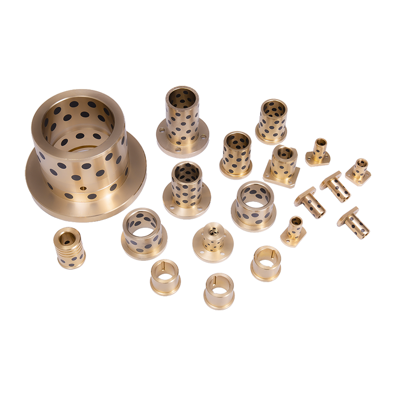
Construction and Material Layers of DU and DX Bushings
The three-layer construction shared by DU and DX bushings is what gives them their exceptional performance density — the ability to carry high loads in compact dimensions without requiring continuous external lubrication. Each layer plays a specific and non-redundant role in the overall bearing performance, and the quality of the interfaces between layers is as important as the properties of the layers themselves.
Steel Backing Layer
The outermost layer of both DU and DX bushings is a low-carbon steel strip, typically 0.7mm to 1.5mm thick depending on the bushing bore diameter and load rating. This steel backing performs two functions: it provides the structural rigidity required for press-fitting the bushing into a housing bore with an interference fit, and it distributes the bearing load over the full housing contact area, preventing stress concentrations that would otherwise damage softer housing materials. The steel is surface-treated — typically copper-plated or given a proprietary surface preparation — to ensure strong metallurgical and mechanical bonding with the bronze interlayer applied above it. In corrosive environments, stainless steel backing variants are available for both DU and DX bushing types, though at significantly higher cost than standard carbon steel versions.
Sintered Porous Bronze Interlayer
The middle layer of both bushing types is a sintered bronze powder matrix, typically 0.2mm to 0.35mm thick, applied to the steel backing by powder sintering. The bronze powder is carefully sized and sintered at controlled temperatures to produce a porous structure with a void volume of approximately 30–40% by volume. In DU bushings, these pores are subsequently impregnated with the PTFE-lead mixture, which fills the bronze matrix and extends slightly above the bronze surface to form the sliding layer. In DX bushings, the pores serve as mechanical anchor points for the acetal resin layer applied on top. The sintered bronze layer also contributes meaningful thermal conductivity to the bushing assembly, helping to conduct frictional heat generated at the sliding surface away from the bearing interface and into the steel backing and surrounding housing, which is critical for maintaining polymer layer temperature within safe limits during continuous operation.
Sliding Surface Layer: PTFE vs. Acetal
This is the layer that most fundamentally differentiates DU from DX bushings. In DU bushings, the sliding surface is a homogeneous mixture of PTFE and lead (typically 75–80% PTFE, 20–25% lead by weight), applied to a total thickness of approximately 0.01mm to 0.03mm above the bronze matrix surface. The PTFE provides the low friction, while the lead serves as a secondary lubricant and helps transfer a thin PTFE transfer film to the mating shaft surface during initial run-in — after which the shaft itself carries a thin lubricating film that further reduces friction. Modern DU-equivalent bushings from various manufacturers replace lead with alternative fillers such as carbon fiber, graphite, or molybdenum disulfide to comply with RoHS and REACH environmental regulations, while maintaining comparable tribological performance. In DX bushings, the sliding surface is a machined or molded acetal (POM) resin layer, typically 0.3mm to 0.5mm thick, providing a stiffer, harder bearing surface with higher compressive strength than PTFE and superior resistance to abrasive particles in the lubricant or operating environment.
Key Performance Parameters: Load, Speed, and PV Limits
The most critical design parameters for any plain bearing selection are the operating load (expressed as bearing pressure P in MPa or N/mm²), the sliding velocity (V in m/s), and the combined PV value (the product of pressure and velocity, in MPa·m/s or N/mm²·m/s). The PV limit is the single most important parameter because it governs the rate of frictional heat generation at the sliding interface — exceeding the PV limit causes the polymer sliding layer to overheat, soften, and fail rapidly. DU and DX bushings have different PV limits reflecting the different thermal and mechanical properties of their respective sliding layers.
DU Bushing Performance Ratings
DU bushings are rated for a maximum bearing pressure of approximately 140 MPa under static conditions and 60–100 MPa under dynamic sliding conditions, depending on the specific grade and operating temperature. The maximum continuous sliding velocity for DU bushings is typically 2.0 m/s under full load, with higher velocities permissible at reduced loads. The combined PV limit for standard DU bushings is approximately 0.10 MPa·m/s in dry, unlubricated service — a figure that may seem modest but is sufficient for a very wide range of low-speed, high-load applications such as pivot bearings, linkage joints, and control mechanisms. When even minimal lubrication is present — such as residual grease, hydraulic fluid splash, or water — the PV limit of DU bushings increases significantly, with some grades rated to 0.50 MPa·m/s or higher in lubricated service. Operating temperature range for standard DU bushings is -200°C to +280°C, reflecting the exceptional thermal stability of PTFE, though load capacity decreases progressively above 100°C as the polymer softens.
DX Bushing Performance Ratings
DX bushings offer a higher maximum dynamic bearing pressure than DU — typically 100–140 MPa under dynamic conditions — due to the greater compressive strength and hardness of the acetal resin sliding layer compared to PTFE. The maximum continuous sliding velocity is similar to DU at approximately 2.0 m/s. The combined PV limit for DX bushings in dry service is approximately 0.05 MPa·m/s, slightly lower than DU in fully dry conditions, but in lubricated service — where DX bushings are specifically optimized to operate — the PV limit rises to 0.15–0.20 MPa·m/s. DX bushings are rated for a narrower operating temperature range than DU: typically -40°C to +130°C, reflecting the lower thermal stability of acetal compared to PTFE. Above 100°C, acetal begins to soften measurably and the load capacity of DX bushings diminishes, making them unsuitable for high-temperature applications where DU or alternative bearing materials must be used.
Side-by-Side Performance Comparison
| Parameter | DU Bushing | DX Bushing |
| Sliding layer material | PTFE / lead (or lead-free filler) | Acetal resin (POM) |
| Max dynamic load (MPa) | 60 – 100 | 100 – 140 |
| PV limit, dry (MPa·m/s) | 0.10 | 0.05 |
| PV limit, lubricated (MPa·m/s) | 0.50+ | 0.15 – 0.20 |
| Max continuous velocity (m/s) | 2.0 | 2.0 |
| Operating temperature range | -200°C to +280°C | -40°C to +130°C |
| Dry friction coefficient | 0.03 – 0.20 | 0.10 – 0.35 |
| Best lubrication condition | Dry or marginally lubricated | Wet or lightly lubricated |
| Abrasion resistance | Moderate | Good |
Typical Applications for DU Bushings
DU bushings are the preferred choice whenever an application demands maintenance-free or infrequent-maintenance operation, whenever external lubrication is impractical or undesirable, and whenever the operating temperature exceeds the range that acetal can tolerate. The self-lubricating property of the PTFE sliding layer — which transfers a thin, tenacious film to the mating shaft during initial operation and sustains low friction indefinitely without replenishment — makes DU bushings the dominant choice across an enormous range of industries and motion types.
- Automotive chassis and suspension: Stabilizer bar links, control arm pivot bushings, steering rack support bushings, and pedal cluster pivots are among the most volume-intensive DU bushing applications. In these locations, maintenance-free service life matched to vehicle service intervals is mandatory, and operating conditions — occasional high loads, oscillating motion, and exposure to road splash and salt — are exactly the conditions where DU bushings excel.
- Agricultural and construction machinery: Loader arm pivots, bucket hinge pins, implement linkages, and tillage equipment joints operate in heavily contaminated environments where continuous regreasing is impractical. DU bushings in these applications are typically specified with additional hardened shaft surfaces (HRC 55–65) to minimize shaft wear from abrasive particles.
- Food and beverage processing equipment: Because PTFE is FDA-compliant and DU bushings require no external lubrication that could contaminate food products, they are widely used in conveyor systems, filling machine mechanisms, and packaging line components where lubricant exclusion zones are mandatory.
- Aerospace and defense actuators: Flight control surface hinges, landing gear actuator pivots, and weapon system linkages use DU bushings for their combination of low friction, high load capacity, extreme temperature tolerance, and complete absence of lubrication maintenance requirements in service.
- Medical and laboratory equipment: Articulating surgical table components, patient handling equipment, and analytical instrument mechanisms specify DU bushings for their cleanliness, consistent low-friction operation, and chemical resistance to sterilization agents including steam autoclave environments.
Typical Applications for DX Bushings
DX bushings are the preferred choice when the application involves continuous or intermittent lubrication — whether from dedicated grease or oil lubrication, hydraulic fluid splash, water ingress, or process fluid contact — combined with higher compressive loads than PTFE-based bearings can comfortably sustain. The acetal sliding layer of DX bushings is harder and more dimensionally stable than PTFE under sustained compressive load, meaning DX bushings maintain their bore dimensions more accurately under heavy loads, which is important for precise shaft alignment and controlled clearance applications.
- Hydraulic cylinders and actuators: The pin joints at the end caps, piston rod eyes, and clevis connections of hydraulic cylinders are classic DX bushing applications. These joints are lubricated by hydraulic fluid that inevitably migrates past seals, the loads are high and often shock-loaded, and the oscillating motion is within the speed range where DX's higher compressive strength provides longer wear life than DU.
- Injection molding machine toggle mechanisms: The toggle linkages of injection molding machines operate under extremely high cyclic loads in a partially lubricated environment — hydraulic oil splash is present but not continuous film lubrication. DX bushings handle the high pin loads and benefit from the available lubrication to keep PV values within limits.
- Marine and offshore equipment: Winch drum bushings, deck crane slew bearings, and anchor handling equipment joints operate in seawater-immersed or splash conditions. DX bushings tolerate water as a lubricant and resist the corrosion that destroys non-protected bronze or cast iron bearings in marine environments.
- Earthmoving and mining equipment track systems: Track pin and bushing joints in crawler-type vehicles experience the combination of high compressive loads, oscillating motion, and presence of water and fine abrasive particles that suits DX bushing properties — particularly in applications where the track joint has a dedicated grease lubrication system.
- Industrial gearbox and reducer auxiliary shafts: Gear shifting mechanisms, auxiliary shaft supports, and oil-bath lubricated auxiliary bearings in industrial gearboxes use DX bushings where the combination of oil lubrication, moderate speed, and high radial load makes acetal the more durable and cost-effective sliding material choice compared to PTFE.
Shaft Material and Surface Finish Requirements
The performance and service life of both DU and DX bushings are critically dependent on the quality of the mating shaft or pin that runs inside them. Unlike rolling element bearings, which have defined rolling contact geometry and can tolerate moderate shaft surface variations, plain bushings operate across a continuous sliding interface where shaft surface roughness, hardness, and material directly determine the rate of bushing wear, the stability of the friction coefficient, and the likelihood of adhesive wear or seizure.
Surface Roughness Specifications
For DU bushings operating in dry or marginally lubricated conditions, the recommended shaft surface roughness (Ra) is 0.2–0.8 μm. A surface in this range is fine enough to allow the PTFE transfer film to develop smoothly and evenly, but not so mirror-smooth that the transfer film fails to adhere to the shaft. Excessively rough shafts (Ra > 1.6 μm) abrade the PTFE sliding layer rapidly, while extremely smooth shafts (Ra < 0.1 μm) can lead to unstable friction and film adhesion problems. For DX bushings in lubricated service, the permissible shaft surface roughness range is somewhat wider — Ra 0.4–1.6 μm — because the presence of lubricant reduces the sensitivity of the acetal layer to surface asperities. However, the general principle that smoother shafts yield longer bushing life applies to both types across all lubrication conditions.
Shaft Hardness Requirements
Shaft hardness is particularly important in applications involving contamination by abrasive particles — soil, sand, metal fines, or process debris — that may become embedded in the bushing sliding layer and then act as a grinding medium against the shaft surface. For DU bushings in clean environments, case-hardened shaft surfaces with a minimum hardness of HRC 45–50 are generally recommended, with the bushing designed to be the sacrificial wear component. In contaminated environments, shaft hardness of HRC 55–65 (achievable through induction hardening, case carburizing, or through-hardening of appropriate alloy steels) significantly extends the effective service life of both the shaft and the bushing. For DX bushings in lubricated service where abrasive contamination is controlled by filtration or sealing, softer shaft materials — including unhardened medium-carbon steel, stainless steel, or even hard-anodized aluminum in light-load applications — can be used successfully.
Installation Guidelines for DU and DX Bushings
Correct installation is as important as correct selection for achieving the designed service life of DU and DX bushings. Both types are supplied in a slightly oversized outer diameter condition — the housing interference fit causes the bushing wall to compress radially inward during installation, reducing the bore to the specified finished dimension. Incorrect installation that distorts the bushing, fails to achieve the required interference fit, or damages the sliding layer will result in premature failure regardless of specification quality.
- Housing bore preparation: The housing bore must be machined to H7 tolerance (ISO standard) for standard DU and DX bushing fits, with a surface roughness of Ra 0.8–1.6 μm. A bore that is too small will overstress the bushing during pressing and can crack the steel backing; a bore that is too large will allow the bushing to spin or slip under load, causing rapid failure.
- Press-fit installation only: DU and DX bushings must be pressed into the housing bore using a properly sized installation mandrel that contacts the full face of the bushing end — never use a hammer directly on the bushing face, as this will distort the thin-walled construction. A hydraulic or mechanical arbor press provides controlled, even insertion force. The bushing should be pressed in squarely — misalignment during pressing creates an elliptical bore that generates uneven loading and accelerated wear.
- Do not ream after installation: DU and DX bushings are designed so that the bore closes down to the correct finished dimension automatically after press-fit installation, based on the standard interference. Reaming the bore after installation removes the PTFE or acetal sliding layer and exposes the bronze interlayer, destroying the bearing's self-lubricating capability entirely.
- Lubrication on installation: For DU bushings intended for dry service, apply no lubricant to either the shaft or the bushing bore during assembly — lubricants contaminate the PTFE transfer film mechanism. For DX bushings in lubricated service, lightly coat the shaft with the system operating lubricant before initial assembly to prevent dry running during the first moments of operation before the lubricant system pressurizes.
- Check bore diameter after installation: Measure the installed bore with a calibrated bore gauge and confirm it falls within the specified tolerance for the shaft running clearance. Typical shaft-to-bushing running clearances for DU and DX bushings are 0.010mm to 0.040mm for shaft diameters up to 25mm, increasing to 0.020mm to 0.060mm for larger diameters. Insufficient clearance generates excess friction and heat; excessive clearance allows shaft movement that causes vibration, noise, and edge loading of the bushing.
Choosing Between DU and DX Bushings: A Practical Decision Framework
Given the overlapping application ranges and similar construction of DU and DX bushings, engineers frequently encounter situations where either type appears technically viable. In these cases, the decision should be made systematically based on the specific operating conditions and priorities of the application rather than defaulting to the more familiar or more readily available type. The following framework guides the selection process through the key decision points in order of importance.
- First, assess lubrication availability: If the bearing location is completely inaccessible for lubrication maintenance, or if lubricant contamination of the product or environment is unacceptable, specify DU. If the bearing will be continuously or intermittently lubricated by oil, grease, water, or process fluid, DX is likely the better choice for its optimized lubricated performance.
- Second, check operating temperature: If the application involves temperatures above 130°C — whether from ambient conditions, process heat, or frictional heating — DX is disqualified and DU must be specified. Below 100°C, both types operate at full rated capacity.
- Third, evaluate bearing pressure against the load ratings: Calculate the actual bearing pressure by dividing the applied load by the projected bearing area (bore diameter × length). If this value exceeds 60–80 MPa under dynamic conditions, DX with its higher compressive strength is the more conservative and durable choice. Below this threshold, both types are viable.
- Fourth, consider regulatory and environmental constraints: For food contact, medical, or clean-room applications, confirm that the chosen bushing type and its specific formulation meet applicable regulatory standards (FDA, EU 10/2011 for food contact, ISO 13485 for medical devices). Lead-free DU formulations are required for RoHS-compliant products.
- Finally, review total cost of ownership: DU bushings in dry service often achieve longer service intervals than DX bushings in equivalent conditions because their PTFE layer continuously replenishes the transfer film without requiring external lubricant. This maintenance-free characteristic reduces total lifecycle cost even if the unit price of DU bushings is slightly higher than equivalent DX bushings.